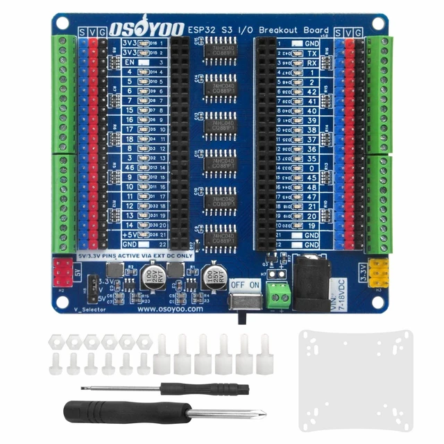
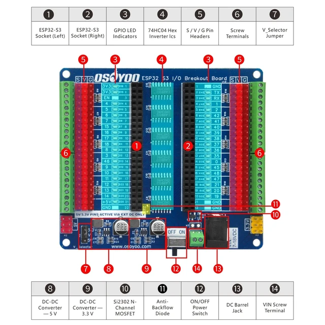
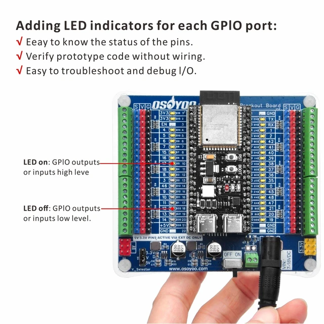
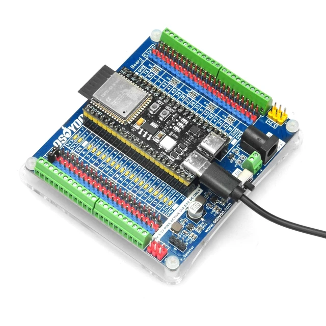
Per-Pin Real-Time Visual Debugging Each accessible GPIO features an independent LED status indicator driven by 74HC04 hex inverter ICs, fully decoupled from the MCU's output stage. Zero GPIO current draw, zero signal integrity degradation on ADC, IC, SPI, or UART buses. LED ON = logic HIGH, LED OFF = logic LOW verify firmware behavior at a glance without oscilloscopes or logic analyzers. ^^ Dual High-Current DC-DC Power Rails Two JW5357MSOTB#TR synchronous buck converters deliver 5V/3A and 3.3V /3A simultaneously far exceeding LDO-based solutions. Capable of driving multiple RC servos, DC motors, WS2812B LED strips, and other power-hungry peripherals with stable, regulated output.
^^ Dual Connection Interfaces + Selectable V-Rail Voltage Each GPIO row provides both a standard 2.54 mm 3-pin header (S/V/G) and a screw terminal block for secure, vibration-resistant wiring. V_Selector jumper allows instant switching between 3.3V and 5V on the common V-rail, accommodating both 3.3V sensors and 5V relay/servo modules without hardware changes. ^^ Comprehensive Hardware Protection SI2302 N-channel MOSFET provides full reverse polarity protection on DC input. Integrated blocking diode isolates the DC-DC 5V output from the USB 5V path, preventing back-feed current when operating on USB power alone. On-board slide switch independently controls peripheral power while allowing USB firmware uploads without disconnecting external loads.
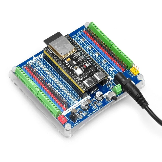
^^ ESP32-S3 Optimized Socket & Wide Compatibility 222P female header socket specifically designed for 44-pin ESP32-S3 development boards, accommodating module widths of 0.8 / 0.9 / 1.0 inch at standard 2.54 mm pitch. Recommended for ESP32-S3-DevKitC-1 (N8/N8R8/N16R8) and compatible with most mainstream ESP32-S3 modules. Comprehensive Arduino IDE tutorials included for immediate out-of-box operation.



 All Categories