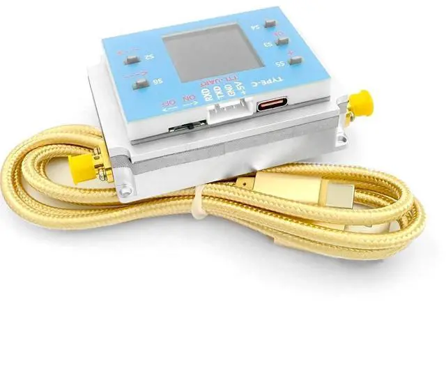
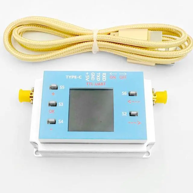
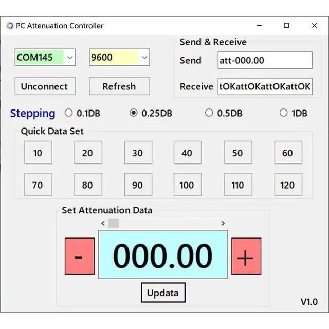
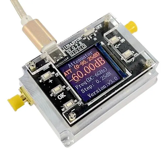
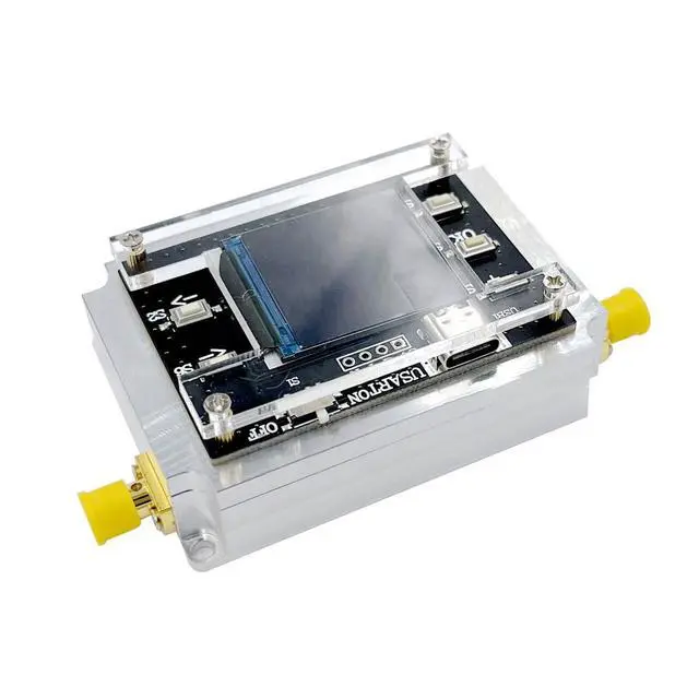
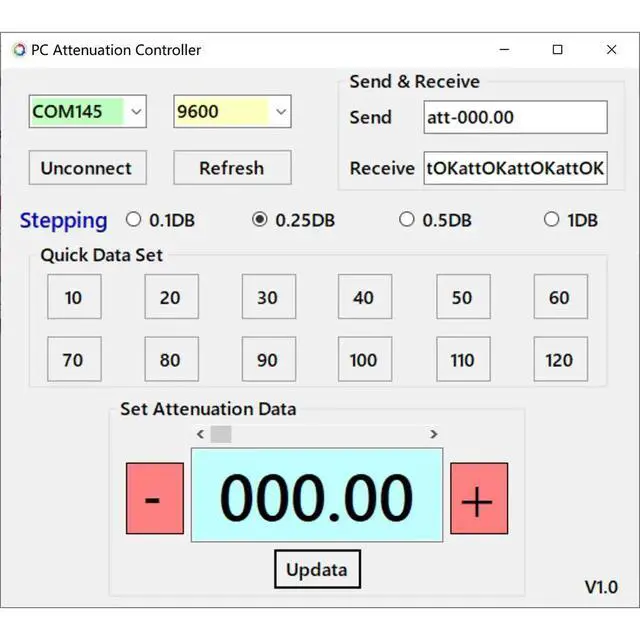
Module Physical Diagram The whole module is made of all - aluminum alloy and adopts a multi - cavity design. The core attenuation chip and the MCU main control are shielded separately. Upper - Computer Communication Software The provided upper - computer communication software is named "PC Attenuation Controller". The main interface has functions such as sending and receiving data, refreshing, disconnecting, and setting the attenuation value. It can select different stepping values ( 0.1DB, 0.25DB, 0.5DB, 1DB) and quickly set attenuation data. Module Measurement DC - 6GHz
Module Measurement: Measured by a vector network analyzer, the attenuation performance at different attenuation values (0, 10, 30, 40, 50, 60DB, etc. ) is shown through graphs. When the attenuation is greater than 60DB, it exceeds the isolation range of the measurement network analyzer. DC - 8GHz Module Measurement (2023
Upgraded Version): Measured by a vector network analyzer, the input loss and attenuation performance at different attenuation values (0, 10, 20, 30, 40, 50, 70, 90DB, etc. ) are measured and recorded in detail. Module Communication Protocol Sending Attenuation Coefficient Command: Used to change the attenuation coefficient. The command format is "att - xxx. xx", and the end symbol is carriage return ("/n/r").
Response Value Signal: The format is "attOK".
FL Serial Port Communication: When using FL serial port communication, the baud rate is
9600.
Reading Data Format: The reading data format is "READ()", and then followed by carriage return.
USB Communication: USB communication is realized through the STM32F4 virtual serial port, and there is no need to set the baud rate.



 All Categories